Coldplay Xyloband Reverse Engineering
The Xyloband is the wristband that Coldplay gives to the audience to create a colorful light show during its concerts.

The wristband receives data from a central transmitter. The new version of the band not only is able to light the LEDs but can receive audio and play it through a built-in speaker.
Contents
Procedure
First, we will disassembly the device and list the different components that we find in the PCB. Then we will try to investigate them looking for datasheets and all the available information to reconstruct the behavior of the circuit. Finally that, we can recover the blueprint of the tracks in the PCB and analyze the complete system.
Disassembly
So I took the Dave Jones approach: “Don’t turn it on, take it apart!”. First I opened the wristband and extracted the PCB with the LED band.
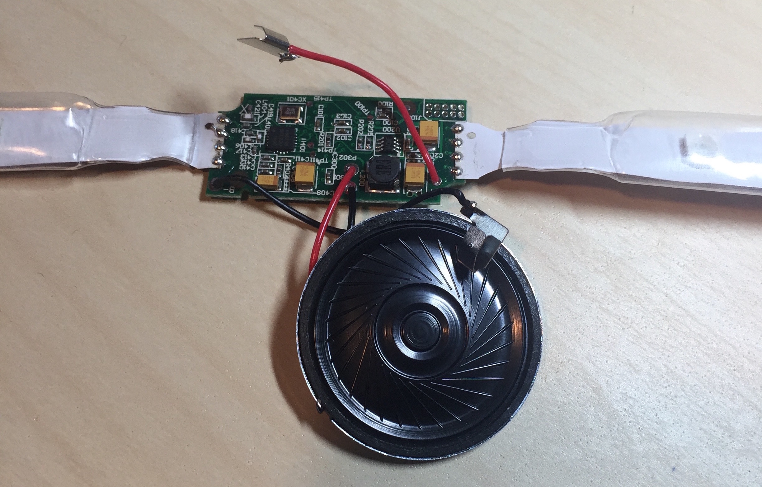
This is the internal parts of the Xyloband. We can see the speaker, the flat-flex with the LEDs and the main PCB. From this view we can intuit that the flat-flex will probably act not only to power the color LEDs but as an antenna to receive the signal.
PCB Inspection
To get a good view of the PCB layers I have done two photos from each side, one front-lighted and another back-lighted. After that we can create a composite image for each side so we can find if there are inside layers. And indeed, there are.

The PCB has 4 layers, two external or sides and two internal layers. In parenthesis is the color I have used later in the PCB track blueprint:
- Front side (Orange)
- Back side (Cyan)
- Internal ground layer (Navy Blue)
- Internal track layer (Purple)
Now we will analyze each layer in detail.
Front
So here is the first composite image of the front side with its main areas, power and data reception, demodulation and decoding (RX):
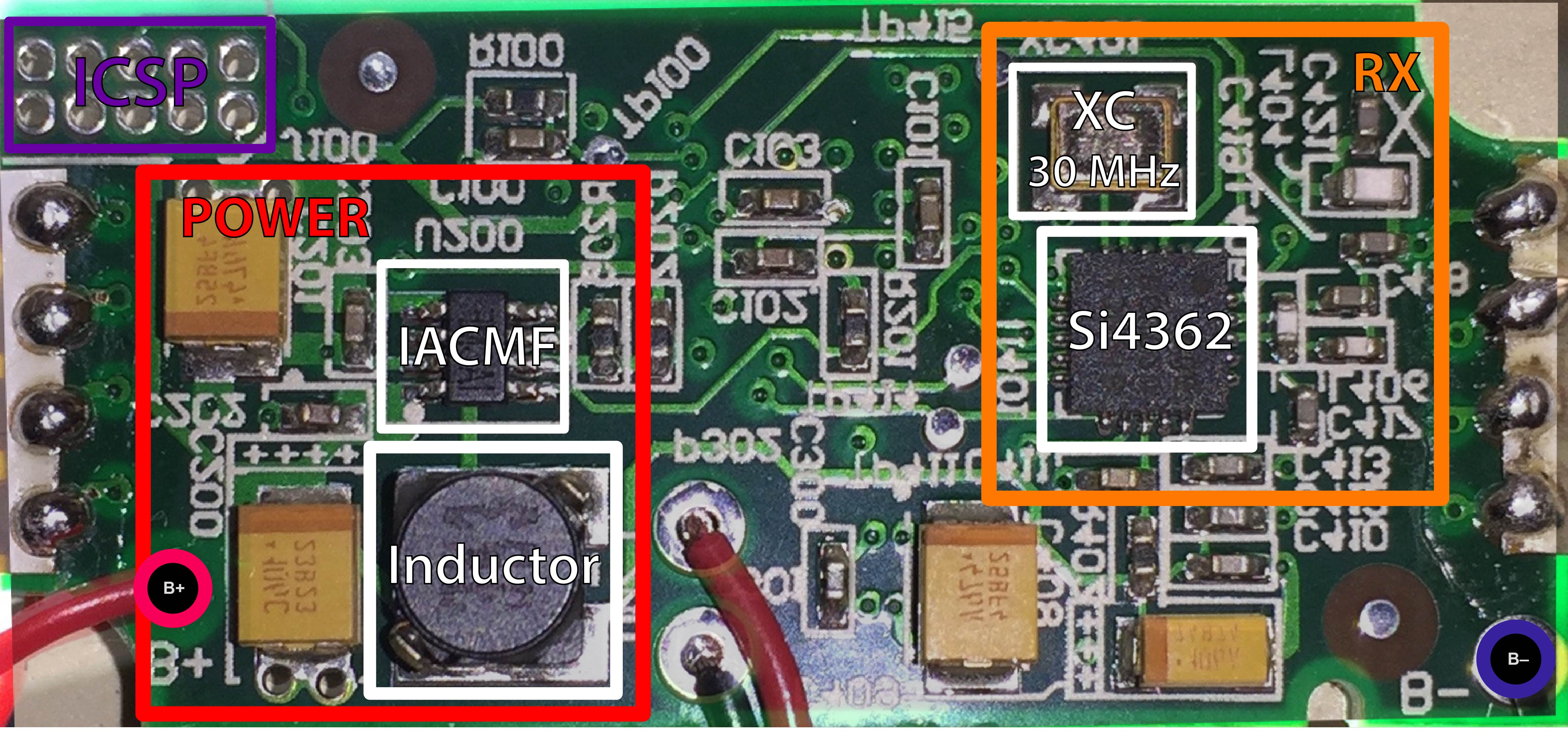
In the front of the Xyloband PCB we can find these devices:
- Silicon Labs Si4362 High-Performance, Low-Current Receiver
- 30 MHz Cristal Oscillator
- IC IACMF Voltage Regulator
- 3 mH Inductor
The Si4362 IC is the main component of the RX area. This chip will receive the transmission from the antenna (we can see it is connected to the uppermost pin of the flat-flex), amplify it using an Low Noise Amplifier and demodulate it. Then the final digital signal will be sent to the microcontroller in the other side of the board through an I²C connection.
The Power section of the front side is mainly a voltage controller that generates the suitable voltage to drive the LEDs and the Audio Amplifier.
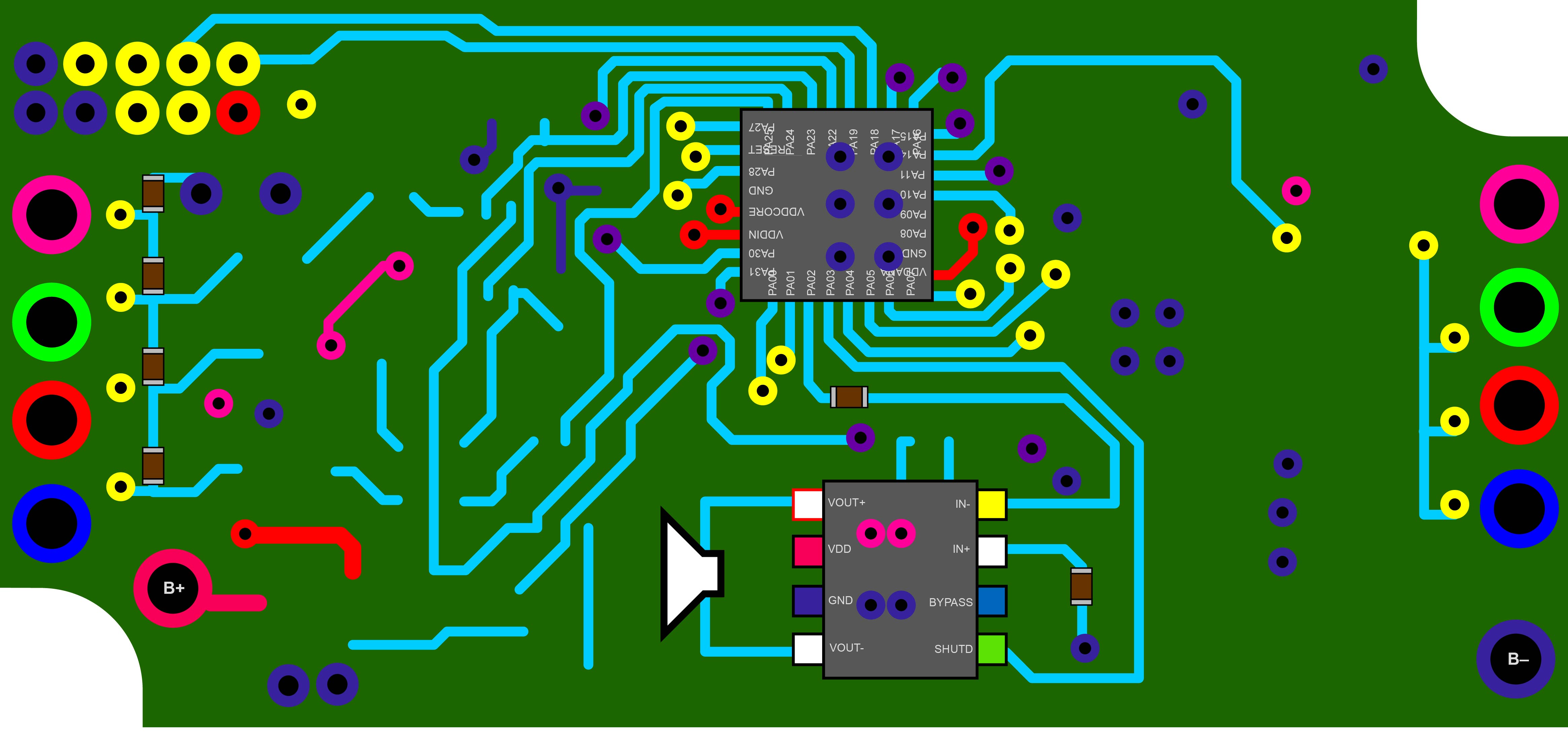
Back
Now back to the back were the main areas are the logic microcontroller, the audio amplifier, the LED drivers and a part of the power section that enables the connection of the battery to the voltage regulator on the other side.
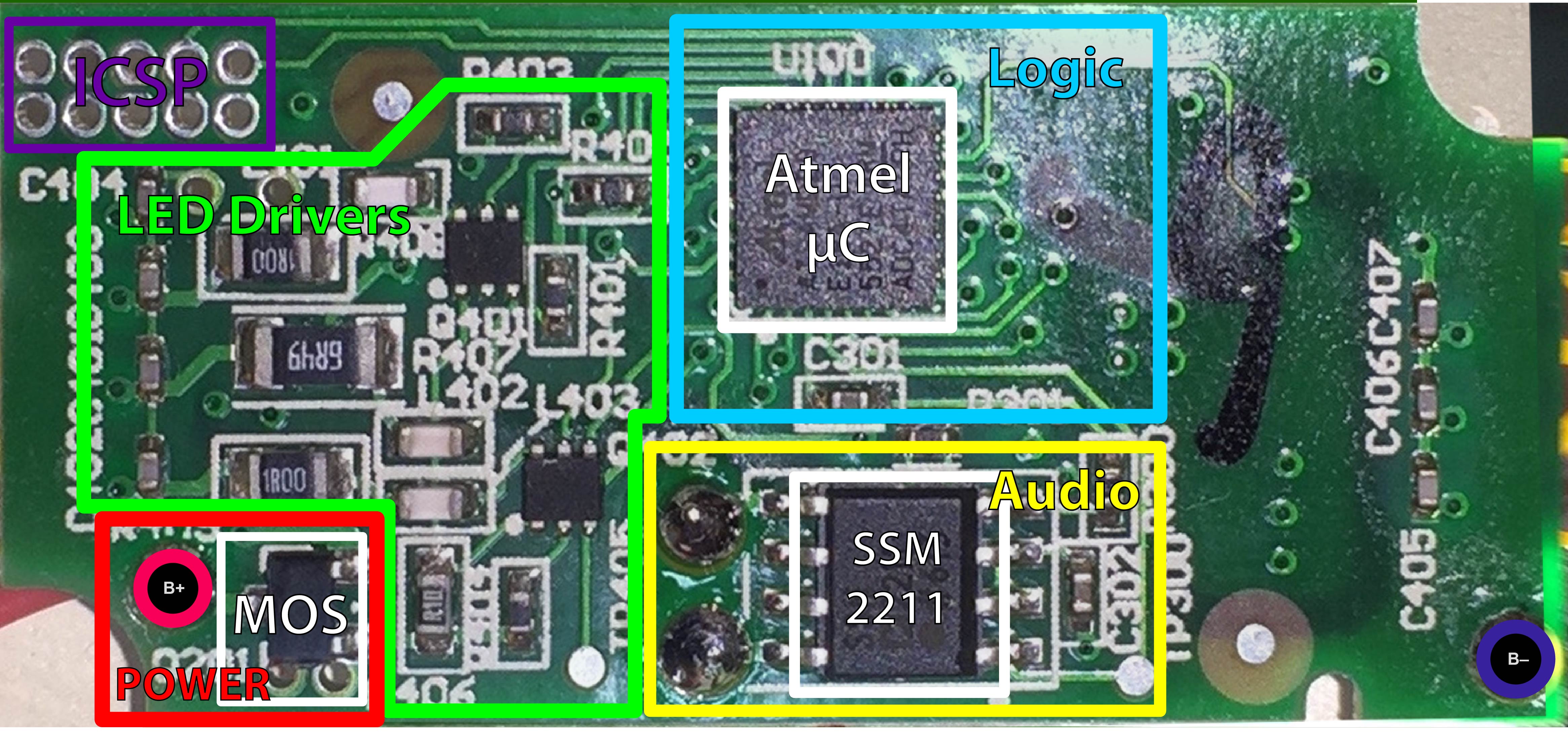
And in the back we can see the following ICs:
- Atmel SAM D20 SMART ARM-based Microcontroller
- Analog Devices SSM2211 Low Distortion, 1.5 W Audio Power Amplifier
The ARM processor is connected with the Si4362 receiver through the I2C and decodes the information, namely the audio and LEDs colors. Then it will light the LEDs through the driver and output the audio signal with its DAC.
The audio signal goes to the SSM2211 audio amplifier which is connected with the speaker.
PCB Reverse Engineering
Now we are going to analyze the board and extract to tracks printed on in to get to full circuit schematic.
Front Tracks
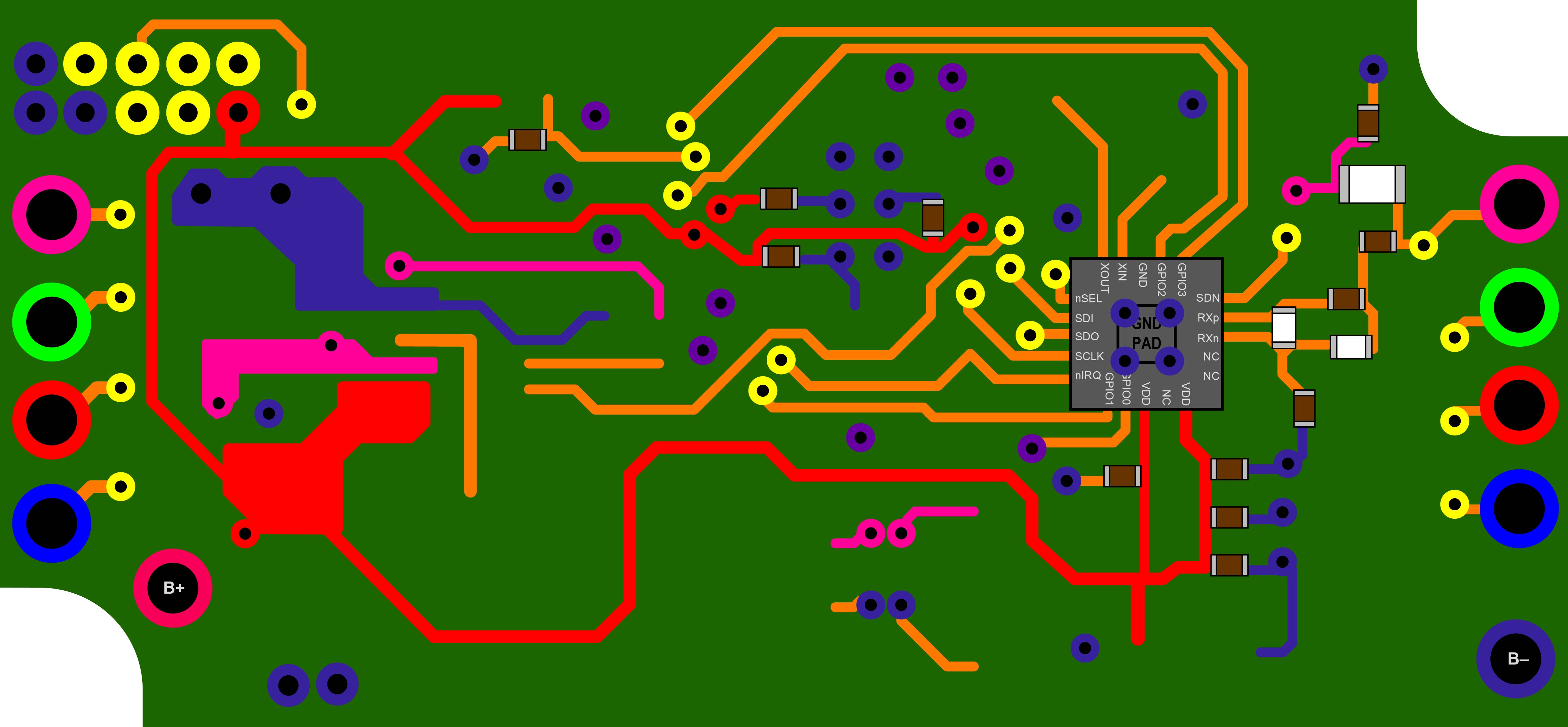
Back Tracks
Inside Tracks

All tracks superimposed
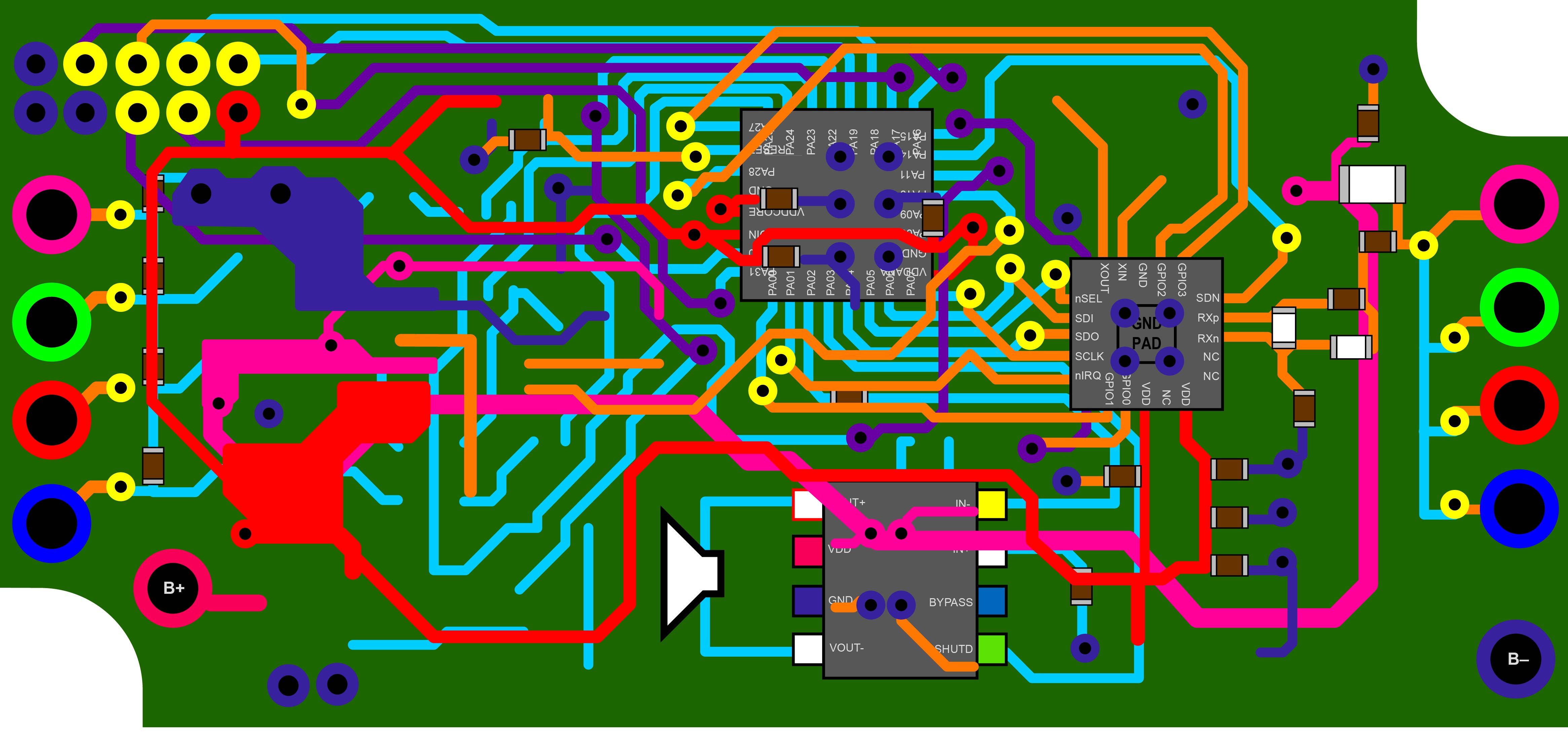
Conclusion
The main controller of the Xyloband is an Atmel SAM D20 which outputs the audio and sets the light of the wristband. The audio output is amplified by the Analog Devices SSM2211 low distortion power amplifier and the LEDs are managed by tree transistors. Finally all the data is received and decoded by the Silicon Labs Si4362 receiver and sent through the I2C bus to the main processor.